LED Series Resistor Calculator
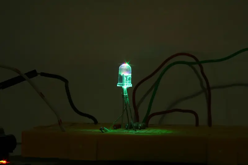
Size the series resistor for one LED string from supply voltage, forward voltage and current, then pick a nearby E-series value and check resistor power.
electronics.tools is a small set of design calculators and learning notes for circuit work. Every tool runs in your browser. Nothing is stored, and there are no accounts.
Enter a target resistance and see the nearest standard E24 value before you open a full tool.
Nearest E24 value
Size the series resistor for one LED string from supply voltage, forward voltage and current, then pick a nearby E-series value and check resistor power.
Find the tap voltage of a two-resistor divider, see how a load pulls that tap down, and check the current and power in each resistor.
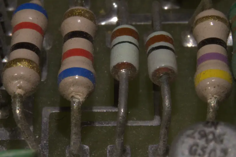
Decode 4-, 5- and 6-band through-hole resistor colour codes to resistance, tolerance and optional TCR.
Combine resistors in parallel or series. See the equivalent resistance and the conductance of the network.
Astable and monostable NE555 timing with exact ln(2) and ln(3), plus reverse astable from frequency and duty cycle.
Solve any two of voltage, current, resistance and power from the other two using V = I R and P = V I.
Size the series resistor for one LED string from supply voltage, forward voltage and current, then pick a nearby E-series value and check resistor power.
Find the tap voltage of a two-resistor divider, see how a load pulls that tap down, and check the current and power in each resistor.
Decode 4-, 5- and 6-band through-hole resistor colour codes to resistance, tolerance and optional TCR.
Combine resistors in parallel or series. See the equivalent resistance and the conductance of the network.
Astable and monostable NE555 timing with exact ln(2) and ln(3), plus reverse astable from frequency and duty cycle.
Solve any two of voltage, current, resistance and power from the other two using V = I R and P = V I.
Pick AMS1117-ADJ resistors with standard values, then check dropout, the 10 mA minimum load and junction temperature before you build.
ASTM B258 American Wire Gauge geometry — diameter, area and circular mils from gauge, or gauge from diameter or area.
Estimate run-time from battery capacity in mAh, average load current and an optional derating factor.
Matched bridged-T pad with arms fixed at Z0. Only the bridge and shunt snap to E96. A above 60 dB is theoretical.
Convert farads, microfarads, nanofarads and picofarads, and decode IEC 60062 3-digit capacitor markings such as 104, 1R5 and 109.
Capacitive reactance Xc at a frequency and RC time constant τ from resistance and capacitance.
Safety discharge time or bleeder resistor from V(t) = V0 e^(−t/RC). Default 60 V is an IEC 62368-1 ES1 DC reference, not a hard legal limit.
Stored energy E = ½ C V² and charge Q = C V. Optional R also reports the RC time constant.
Pick the right CH340 variant by crystal, package, modem lines, temperature and 3.3 V supply, with the WCH pin differences and baud-error figures for each.
Split a source current among parallel resistors. Ik = I·(1/Rk)/Σ(1/Ri). A 0 Ω branch is a short and is rejected.
Convert between dBm, watts and dBW. 0 dBm is 1 mW; 30 dBm is 1 W; dBW = dBm − 30.
JEDEC JESD51 stack Tj = Ta + P(θJC+θCS+θSA), Pmax, and the θSA required to stay under Tjmax. No uncited package θ table.
Design R2 = |G|·R1 and bias-compensation R3 = R1 for a target inverting gain, with optional level-shift R4 and nearest E24/E96.
Set LM2596-ADJ output with standard resistors, get the inductor E·T value TI uses, and check minimum input voltage for TI, onsemi or XL2596 parts.
Set MP1584 output and frequency resistors, size the inductor and check the 100 ns minimum on-time. MPS lists MP1584 as not recommended for new designs; see what changes with MP2338.
Ideal four-resistor op-amp superposition (Sedra/Smith) with differential, inverting and non-inverting presets, then clip Vout to the rails.
IPC-2221A internal and external copper trace width from current, copper weight and temperature rise, with DC resistance at Tamb + ΔT.
Matched π-pad resistors from A and Z0, plus nearest E96 and the back-calculated voltage attenuation. A above 60 dB is theoretical.
Compute DC power and the third quantity from any two of voltage, current and resistance using P = VI, I²R and V²/R.
τ = R C with charge and discharge voltages at 1τ through 5τ, stored energy, charge and cutoff frequency.
Xc = 1/(2π f C) and Xl = 2π f L, plus inverse L or C from X and f, and susceptance |B| = 1/|X| in siemens. Frequency in Hz–GHz.
Reflection pad Rhi/Rlo from A and Z0. Requires a 90° hybrid coupler. A above 60 dB is theoretical.
Parallel Cp = Σ Ci and series 1/Cs = Σ 1/Ci from a list of capacitors. Series mode always flags unequal DC voltage sharing.
Decode EIA-3, EIA-4, EIA-96 and R-notation SMD resistor markings. Ambiguous codes such as 10R show both readings.
Matched T-pad resistors from A and Z0, plus nearest E96 and the back-calculated voltage attenuation. A above 60 dB is theoretical.
Calculate TL431 divider resistors with Iref error, the valid cathode-resistor range for your input and load, and SOT-23 power and temperature rise.
Set TP4056 charge current from RPROG, check chip temperature at your battery voltage, and see why "1.2k = 1A" tables disagree with the datasheet.
Convert resistance, voltage, current, capacitance, inductance, frequency, time, power and energy with SI prefixes.
Datasheet-checked equivalents and SOT-23 marking notes. A verdict only applies under the conditions listed with it.
TI LM1117, ST LD1117 and JSCJ CJT1117B checked line by line against the AMS1117 datasheet: SOT-223 pinout, dropout, min load, capacitor and heat.
What changes when you swap a CH340G: pinout, crystal, supply, baud rate, temperature and USB IDs for CH340C, CH340E, CP2102 and FT232RL, from each datasheet.
TI LM2596, onsemi LM2596 and XLSEMI XL2596 compared pin by pin: saturation voltage, duty cycle, current limit and ON/OFF thresholds. XL1509 needs a new layout.
Decode TI TL431/TL432 SOT-23 (DBZ) markings into grade (0.5/1/2%) and temperature range, from TI's package addendum, and avoid the TL431 vs TL432 pin swap.
Short notes on formulas, passive values, and common footprints — each linked to a calculator where it helps.
Convert mAh to runtime with load current and efficiency factors.
Xc and Xl at a frequency with links to the reactance calculator.
Ceramic, electrolytic, and film capacitors — where each belongs in a board.
Footprint codes for resistors, capacitors, and small ICs — facts only, no substitution guarantees.
Selection criteria and widely used part numbers to orient a BOM — not a catalog or storefront.
Switching regulators for efficient step-down rails.
Dielectrics, voltage derating, and bypass placement.
Bulk input and output capacitors — ripple, ESR, and lifetime.
Rectifiers and switching diodes for protection and ORing.